| |
| |
Anzeige/WerbungPlease pay attention: new version available: Model C
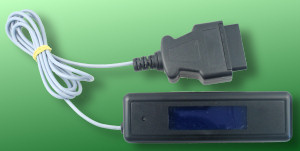
OBD II LCD Modell B - The multi-function display for the permanently display of car datas
Deutsche Version auf extra Seite.
Content
New Version
Entering guide
Start-up
Operation
Measured values/PIDs
Assembling
Entering guide
Version 2.5 offers as a new function a complete bilingual view of all menu options and data values! At every time you can choose between german and english as display language.
The OBD II LCD Modell B is used (like the pre version) to display diagnostic data in an car without additional hardware. On a 4 x20 chars big display (4 lines with 20 chars) you can permanently view up to 8 measured values. So it is possible to always have important information about the operating condition of the vehicle in the view.
Particularly with modern cars the manufacturers save again and again important display elements in the cockpit. Thus frequently a tachometer or the temperature indication for the cooling agent is missing. With the multi-function display you can re-tool this comfortably and without installation expenditure. Thus you avoid critical operating conditions as for example a "cooking" engine and you can aim an economical driving fashion, in which you drive in the ideal speed range and with smallest engine load - nearly ECO Tuning.A further bonus is that the vehicle speed is very precisely indicated and without the usual inaccuracy of the speed gauge. With many (often diesel fuel) vehicles instead of the cooling water the oil temperature is supplied.
Additionally you can query also exhaustrelevant error codes, which were recognized by the self-diagnostic system of the vehicle with the display now. Both the permanently stored errors (SID 03), and the temporary (SID 07) can be selected and be indicated in the standardized ISO/SAE error code. Thus you know exactly, which construction units are damaged and do not drive on ignorantly and if necessary further systems damage, because you did not get the error indicated by the vehicle. After effected Raparatur you can clear the error memory with the OBD II LCD even again.
As soon as an error in the vehicle is stored, a clear reference appears on the LCD: At first position an inverted exclamation mark in the change with a tool key symbol and the text "failure" are indicated.
Example of the announcement of a measured value in specially large representation.
Functions:
- Up to eight measured values at the same time approximately in real time - individually configurable
- Extreme large representation of an individual measured value for optimal reading off quality
- OBD II Parameter (depending upon vehicle differently available):
- Speed (material and without the inaccuracy of the normal tachometer)
- Engine Speed
- Coolant Temperature (with Diesel often oil temperature)
- Air intake temperature
- Engine load value
- Ignition Timing Advance
- Absolute throttle position
- Measured values O2 Sensor
- Supported OBD standard
- and further...
- Additional measured values and computations:
- Battery voltage
- Momentary consumption in l/100 km
- Momentary consumption in km/1 l
- Warning in the case of stored errors (DTCs)
- Number of errors in SID 03 and 07
- Auxiliary functions:
- Acceleration measurement 0..100 km/h
- Display of all stored error codes in SID 03 and 07
- Delete all stored error codes etc.
- Calibration of the Voltage measurement
- In two languages: German/English at any time selectable
- Adaptive display brightness: Display is darkened automatically with little environment light, in order to reduce the glare
- Modern blue or particularly white display which can be read off well during direct sun exposure intended
- Installation into small housing (approx. 129 x 40 mm) or individual installation into the vehicle armatures possible
- Simplest start-up: simply put into the OBD II socket of the vehicle
- Very few current consumption: less than 40 mA during operations
Start-up
To operate your vehicle must possess OBD II or subfunctions of it. The display supports only vehicles with the OBD II protocols ISO 9141 and ISO 14230 (KW 2000). In the vehicle list you can see, at which vehicles the display was already tested or which protocol use your vehicle. Vehicles, with which the pre version (as "OBD II LCD" named) functioned, can be addressed also by the new OBD II LCD Modell B. If your vehicle is not located in the list, it does not mean that the display will not work, but only that me so far no information is present.
Please you consider the numerous assistance: FAQ, discussion group (you can ask in english!), soldering. Inform about OBD II and the pre version of the OBD II LCDs.
The developed module can be inserted into a separately available housing of the type 2090, which already possesses the necessary cutout for the LCD and a hole for the button. Alternatively the equipment can be used also directly in the car behind an existing screen.
If you attached the OBD II plug to the module, for these you only put it into the OBD II socket of the vehicle. Alternatively you attach also the three connecting cables (vehicle battery +12V, ground and K-Line) directly to appropriate lines in the vehicle (for example of the back of the OBD socket), if the plug would disturb. Note please that you take the module off the plug or by separation by a separate switch (k-line or +12 V), if other diagnose units are to be attached.
The module has the new kind of the recognition whether the ignition is on. Each time as soon as the plug is put in, the display lights up and shows the greeting screen with program name, version number and the reference that the ECU (Engine Control Unit) is looked for. The increasing number at points refers to the search. If no ECU is found, because the ignition is out or the display cannot co-operate with the vehicle, the announcement expires and the LCD becomes dark.
The equipment tries now to connect itself again and again with the ECU. That costs only minimum current and discharge the automotive battery not noticeably. If you turn the ignition on, after a short while (up to approx. 10 seconds) the display becomes activates, if the module can communicate now with the ECU (otherwise it remains darkly). Subsequently, the measured values are shown or it appear the reference to new engine expensive equipment (see below). If you start the engine it can be that the display must make a connection to the ECU again. That is completely normal and unproblematic. They can to be started your car as used without respect on the display. After turning the ignition off the display switches itself off automatically. This can take approx. one minute with some vehicles, since the Engine Control Unit continues to work still briefly.Operation
With first start-up (current it put on first) the display recognizes that still no language selection was met and you be able to specify the language: Through the key can you press the next point of selection mark. If all entries were gone through, it begins with the first entry again. If you do not press a few seconds the key, the straight marked selection is taken over. This will be happen also, if you do not press the key; then German is selected as language. They can change the language attitude at any time over the menu (see below).
After the display an ECU found, it indicates the connecting parameters briefly.
If the display was so far not used or was not used in a new vehicle (other controller), a reference appears on the fact that the represented measured values (PIDs: Parameters Identifier) ca adjust. Press once briefly on the key.
- The following configuration is identical to the later Umkonfiguration over the menu entry PIDs Selection.
The cursor flashes at the position for those to be indicated the measured value which can be adjusted now.
If you do not press a few seconds the key, the attitude is taken over and the next representation position started and/or terminates the configuration, if all available positions became to go through.
Each pressure on the key indicates the next measured value and/or the next representational form. If all measured values went through, a blank can be choosen, so that the selected position remains empty. Subsequently, again the first measured value is indicated. Depending upon position on the LCD with each depressing the key the next possible representational form is indicated. If all forms for the PID went through, the next PID is indicated and again the possible representational forms are gone through.
- Which measured values (PIDs) are available, is vehicle specific. Some values can be indicated with each vehicle (see below).
- For most values there are three representational variants:
Short representation with shortened description. Per line two short representations can be choosen.
Specially large. This representation can be stopped only, if the cursor stands at the beginning of the first line. No further values on the display can be indicated. In the first line the description and the three continuation lines are located for the number notation are used.
Occur an error during the large representation as usual in the first place the error note is indicated. However then no measured values can be indicated, since no values for the further positions were configured.
- After all display positions became to go through, the attitudes are stored and are used in the future. The display indicates the measured values now endlessly. The configuration can be changed at any time.
Press during the measured value announcement the key somewhat longer, until the menu appears.
- Through the key you can press the next menu option mark. If all menu entries were gone through, again with the first entry one begins. If you do not press a few seconds the key, the straight marked menu option is selected.
Select the entry Abort/Back, if you want the menu to leave and again return to the measured value announcement.
Select Show Errors, To let indicate to view all stored errors (permanent: SID 03, temporarly: SID 07) of the vehicle.
The first screen shows an overview, how many errors are put down.
- Press the key, in order to see the first error code. The error codes correspond to the ISO/SAE sets of rules. You find a complete description of plain language of the codes in the book Fahrzeugdiagnose mit OBD.
It is indicated to you, which error memory is that-shown indicated (SID 03 or 07) and the how many by many errors (DTC: diagnostic trouble codes). In the example first (with the error code P0100) is indicated by three permanent errors. With each depressing the key the next error is indicated. First all permanent and afterwards all temporary errors. After the announcement of the last error code you arrive after depressing the key back at the measured value announcement.
After you called the menu (again), you can also delete the error codes. Please you note that through it important service information to be lost and also different error memory and the Readinesscode is put back. You can delete only everything, not individual errors. Clear the errors only, if you really repaired the error cause. Select Clear Errors.
A safety inquiry appears. Select Yes similarly to the menu selection, if you want to really clear the error memory. With No/Abort you return to the measured value announcement. To the deletion the program returns to the measured value announcement. If necessary you can through (renewed) indicate the stored errors examine whether all DTCs was deleted or new is registered.
After you called the menu (again), you can accomplish the calibration for the votage measurement: Voltage Calibr. The voltage measurement indicates, how much volt supplies the automotive battery and/or as high the on-board voltage is. The measurement takes place with a simple circuit, which permits no high accuracy and supplies only a rough appoximate value. In order to optimize the indicated value, the circuit can be calibrated with the help of an additional voltmeter (circuit analyzer).
- Switch on only the ignition, no engine run. Switch all consumers (ventilation, radio etc..) out. Measure with a suitable measuring instrument the voltage at the automotive battery.
They can now enter the measured voltage, so that the OBD II LCD can adapt the internal voltage calculation. The measured voltage is indicated in two places before the decimal point and two decimal places positions. The cursor shows, at which position it straight.
Through press the key you can select a number for this position (0..9). After you concerned at 9, again with 0 one begins. Enter if necessary in the first place to 0. If you do not press the key a few seconds, the next position is started and/or locked to the fourth place the input and to the measured value announcement returns.
After you called the menu (again), the acceleration measurement of the vehicle is to you at the disposal: Sprint 0..100.
If the vehicle drives, the current speed is indicated and you be supposed to be stopped.
As soon as you stand still, the measurement can begin.
Accelerate the vehicle. The current speed and the time needed so far are indicated.
As soon as you are stopped either again or 100 km/h reached, the measurement is final and the necessary time is largely indicated to you.
- Press the key, in order to return again to the measured value announcement.
After you called the menu (again), the language attitude is to you for the display at the disposal: Sprache/Language.
Measured values/PIDs
The following table shows the representational form for all measured values and PIDs in the display in long and in short way of writing:
The announcement of the momentary fuel consumption is experimental. On the basis several measured values approximate present gasoline consumption is computed. If the necessary PIDs is not offered by the vehicle, a computation cannot take place. Since for the computation several measured values must be queried, the representation is somewhat retarded. With diesel engined vehicles a value can be computed, these is however with security wrong. As exactly the indicated value with a petrol car of the reality corresponds cannot so far not be said.
PID Function long representation (exemplary) short representation (exemplary) specially large representation possible Meaning - Expenditure of ISO-Norm and the available PIDs No Fast Init/Slow Init (ISO 14230) or 9600/10400 Baud (ISO 9141); always available 1 System Status No Number of stored permanent errors 2 DTC that caused required Freeze Frame Data storage No 3 fuel system 1 status No Open/closed loop without error; closed loop = "Driving/Dr"; Open/closed loop with error 4 Calculated load value Yes 5 Engine coolant temperature (water/oil) Yes 6 Short Term Fuel Trim Bank 1 Yes lean (<0) to fat 7 Long Term Fuel Trim Bank 1 Yes 8 Short Term Fuel Trim Bank 2 Yes 9 Long Term Fuel Trim Bank 2 Yes 10 Fuel Rail pressure Yes 11 Intake Manifold Absolute Pressure Yes 12 Engine speed Yes 13 Vehicle speed Yes 14 Ignition Timing Advance Cylinder 1 Yes 15 Intake Air temperature Yes 16 Air flow rate from Mass Air Flow sensor Yes 17 Absoulte Throttle Position Yes can be also position of the gas pedal 18 Commandes secondary air status No upstream, downstream, Off, unknown 19/29 Location of O2 Sensor No Number value in accordance with ISO (s. ISO 15031) only with long form 20-27 O2 Sensor output voltage & Short Term Fuel Trim No Bank 2, Sensor 3: voltage value and correction value; no announcement of the trim value during short form 28 OBD Standard No and so on 30 Power Take Off status No On/Off or 1/0 31 Time since engine start No 32 Supported PIDs after PID 32, which is not interpreted by the display No - Number of error codes in SID 03 and 07 No always available - Fuel consumption km/1 l Yes - Fuel consumption l/100 km Yes - Battery Voltage Yes always available - Blank No Blank; always available Assembling
The individual construction units you must solder in accordance with the guidance. It concerns except for an exception thereby "normal" wired construction units, which can be developed by somewhat experienced hobby electronics engineers in approximately 30..60 minutes. The only SMD construction unit can be soldered in addition, still well and problem-free.Circuit diagram:

Construction unit list::
Quantity Identifier Type 2 R1, R2 10 kΩ (brown - black - orange) 1 R5 510 Ω (green - brown - brown / green - black - black - brown) 1 R6 22 kΩ (red - red - orange) 1 R7 6,8 kΩ (blue - grey - red) 1 R9 18 Ω (brown - grey - black) 1 R3 250 Ω Poti 6mm 1 R4 2,5 kΩ Poti 6mm 2 C1, C2 22 pF, RM 2,5 1 C3 22 µF/35 V RM 2,5 6x5 mm 1 C4 220 µ/6,3 V RM 2,5 6x5 mm 1 C5 100 nF, RM 2.5 1 C6 10µF/25V RM 1,5 4x5 mm 1 D1 1N4004 1 D2 SFH309 1 D3 1,5KE18A 1 D4 SB130 1 T1 BC547 1 IC1 ATmega32 1 IC2 LM2574-5 1 IC3 MC33290 1 F1 MF-R 0,2A 1 JP1 6x pin row RM 2,5 1 L1 47µH/450mA 1 L2 470/680µH/280mA 1 LCD LCD 204x-4NLW 1 Q1 8 MHz 1 S1 Button 13 mm 1 D-SUB-Plug, 9-pins, soldering cup With the circuit Design much importance was particularly attached to it to protect the electronics before extreme voltage peaks, as they arise in a car. Therefore some fixed inductances and a switch power pack were integrated. The circuit delivers no warmth and to no cooling requires. The independently resetting safety device prevents itself damage.
- If you want to change the display brightness and the contrast at any time later with closed housing, you can bore two holes into the back housing bowl. Put in addition the plates into the housing bowl (assembly print downward). In the axle center of the trim potentiometers holes are bored into the plate, so that you can transfer the position more easily to the housing bowl.
Solder in accordance with the construction unit list and the assembly print all construction units on the PCB. Construction units are equipped on both sides of the plate. The later front plate (the side on that the LCD sits), is the solder side of most construction units in the first work procedure. The component side (side with assembly pressure) of most construction units will be later the back!
- IC1, IC3, JP1, S1 and the LCD yet do not solder.
- Pay attention to solder the construction units very flat. F1 if necessary put flat.
- With L2 the outline of the construction unit in the assembly pressure is missing. The correct position is to be recognized however by the photo and is obvious, if the other construction units are inserted.
- Pay attention not to set Q1 concisely the plate. The metal housing short circuits the two pads. Left small little air between housings and plate with solder!
- The photodiode D2 is aligned with the flat side to the crystal. The diode is to rise up later by the housing and provides for the adaptive brightness adjustment of the LCD lighting. Before that solders is to be considered, as and where the equipment is fastened later in the vehicle and like then the diode must be aligned (to the rear out, upward, forward showing etc.). According to it the wires must be bend or solder the diode to the front side (further to the polarity pay attention!)
- Test the past structure.
- Put approx.. 12 V and mass to the ports VCC and GND.
- Measure the voltage at pin 1 of IC2. This must amount to rather accurately 5 V.
Solder the ATmega µC.
Solder IC3 on the front.
On the front side equip you JP1 and S1. JP1 is needed only if you want to program µC with an self-development (code etc. is not offered!) and/or want to test the structure in the following step with an existing ISP adapter.
- If you possess an ISP adapter, you can test the structure: Supply voltage attach like already before and conenct with the ISP adapter. With the help of the PC programming software try to find/identify to the ATmega. If the software knows the processor address/responds all is OK.
On the front side equip you the LCD.
- Pay attention to the correct adjustment. Soldering pad 1 is rectangular implemented instead of round on the plate. The broader side of the metal frame of the display front must point to the tracer.
- Since it is extremely laborious to out-solder the LCD without destruction later if the equipment does not function, you can connect all pins also for a test with a short wire (max. 10 cm) with the respective solder pads.
- At the bottom surface of the LCD module are metal noses, those connect the frameworks with the actual display, the display plate and the rubber contact lying between them. These noses are partly somewhat too long and affect the soldered connections on the plate of the OBD II LCDs. Therefore the LCD module must be used for a test. Then easily flat bend or rotate individual metal noses very carefully, so that no short-circuit between solder tack and LCD module develops. On the fact it respects that the LCD does not stand mechanical forces and the light-grey rubber contacts is not damaged or is not deformed.
The plate of the OBD II LCD is now finished developed.
- The module can be connected in two kinds with the vehicle:
- Over a three-core cable to that if necessary a OBD II-plug is soldered on or its lines directly with the appropriate lines in the vehicle to be firmly connected:
Solder the cable to the three soldering pads K (OBD data k-line), VCC (battery plus) and GND (battery minus/mass).
- Ever after as and where you fasten the module in the car, you can lead the cable completely as desired from the housing, to which they must bore an appropriate hole in the housing to the suitable place.
- By the two holes next to one another you can thread the cable, in order to manufacture a strain relief.
Solder if necessary the OBD plug in accordance with connection allocation on (pin 4/5, 7 and 16). Connect for safety's shorten the pins 4 (vehicle mass) and 5 (signal mass) in the plug.
- With a OBD-2 standard cable to Sub-D:
Solder a 9-pole male SUB-D plug to the solder points. Pay attention to align the plug correctly.
- You must work on the housing in such a way that at the right side a cutout for the plug becomes free.
- You can connect the OBD module now by the OBD-2 standard cable with the OBD II-socket of the vehicle.
- Apply supply voltage (approx. 12 V). The LCD must light up and the greeting screen (program name etc.) show. There is necessarily mostly still two attitudes on the trim potentiometers. If the module is not connected with a vehicle, no ECU is found and the display switched off after a few seconds. Separate then if necessary simply from supply voltage and connect again.
- If you do not see anything or only a bright surface, turn the contrast, until the letters become well readable. The optimal contrast attitude depends on the reading off angle later in the vehicle.
- Darken the photodiode D2 well. Turn at the potentiometer for the brightness, until the display becomes darker. Light up D2 now with bright light. The LCD background lighting should become brighter. Select an attitude for the trimmer, which fits your brightness desire. If you do not wish adaptive darkening, turn the potentiometer up to the stop position with maximum brightness.
- Put the module into a housing bowl to determine, where you must bore the hole for the photodiode.
Since the assembly columns are a little too short, thin shims with approx. 0.8 mm on the columns present and if necessary with second adhesive fix, so that they do not down-slip when the assembling always.
The pane must be bonded into the housing overhead panel. Only very little superglue use, press in slightly so that these not flow by the capillary action with into the visible range.
- Assemble housings. Finished!